Quad VCA

Quad Voltage Controlled Amplifiers
This module is based on circuits described here by Philip Gallo, and based on Mike Irwins circuit for creating a linear VCA with the SSM2164 Quad VCA chip. CoolAudio currently manufactures the V2164 clone of the SSM chip.
Each VCA is switchable between a linear or an exponential response.
My build switches response in pairs- each VCA can be individually switched
I left my original artwork on the panel. My first DIY builds used Photograhic RC paper as panel artwork. This is the last module to have it still.
LW panel photo courtesy of Charlie Kerr/Loudest Warning

VCA Build Notes
*See important information below or in build docs
The current PCB has an error in the voltage reference circuit which reqires installing the eltectrolytic capacitor backwards, and installing the resistor in an alternate location. See the artwork below or in the build documentation download
Current build is Version 1.0
Download documentation here:Quad VCA documentation
All parts are currently easily available
The V2164 chip is available from Smallbear Electric and the NEC EC2-12NU relay is available from either Mouser or DigiKey. All other parts are garden variety. I used OPA2134 for the audio path op amps but TL072s will work also.

Diode installation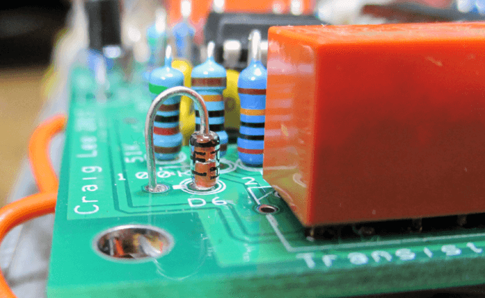
Install all diodes stripe (Cathode) up, with the body over the circle on the silk layer
Using a Zener Diode in place of LM4040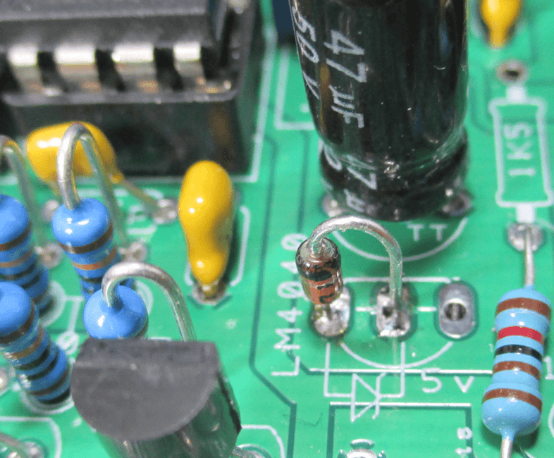
A 5.1v zener diode can be used in place of the LM4040. Silk screen drawings for both are included.
AS POSTED by David Dixon HERE and discovered by another builder on Muffs, offset voltages in the linear mode CV circuit can cause leakage when the VCA is off. Installing 10meg resistors between the neg 5V ref and the summing node will cut out any leakage.

Install the 10meg resistors as shown
*IMPORTANT*
The current PCB has an error in the voltage reference circuit which reqires installing the eltectrolytic capacitor backwards, and installing the resistor in an alternate location.
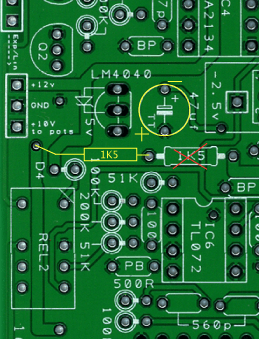
Install Electorlytic with the + and - sides reversed
Install the 1K5 resistor where shown, with one end connected to the via for the negative supply
DO NOT INSTALL a resitor in the area "X'ed" out